- 您现在的位置:买卖IC网 > Sheet目录347 > P0305 (Terasic Technologies Inc)KIT MAX II MICRO
MMK User Manual
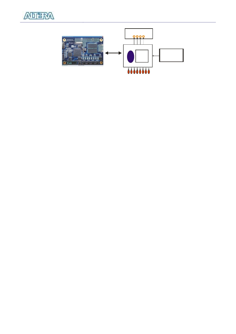
Prototyping Area
USB
Blaster
IP
USER
IP
Pushbutton
Switches
LEDs
Figure 3.3. The MAX II Micro Control Panel concept.
Using the Control Panel
3.2
14B
The interface of the MAX II Micro control panel window matches the real MAX II Micro board.
Users can select the components they want to control directly. All configurable components are
marked with blue frame in the window.
The MAX II Micro Control Panel can be used to light up LEDs, detect the pressed action of
pushbutton switches and configure the I/O logic level of prototyping area on the MAX II Micro
board. The following sections describe how to perform these actions with the control panel already
open on the host computer
Typical design activities do not require the ability to set arbitrary values for simple display devices.
However, for troubleshooting purposes, setting arbitrary values enables you to verify that the
devices are operating correctly.
? Light up the LEDs
To light up the LEDs on the MAX II Micro board, you can turn the individual LEDs on by
clicking the LED icon on the control panel window as show in the Figure 3.4. The icon of the
chosen LED will be marked with yellow color.
15
发布紧急采购,3分钟左右您将得到回复。
相关PDF资料
P0528
BOARD DEV DE1 ALTERA
P100-001
ADAPTER DB9F TO DB25M 1'
P2041RDB-PA
BOARD REFERENCE DESIGN P2041
P25E-060S-EA
CONN SOCKET 60POS .050" GOLD
P25E-100S-EA
CONN SOCKET 100POS .050" GOLD
P25LE-068S-DA
CONN SOCKET 68POS .050" GOLD
P302-06I-R
CABLE SPLITTER DB15 M-2F 6"
P302-06I
CABLE SPLITTER DB15 M-2F 6"
相关代理商/技术参数
P0306
功能描述:可编程逻辑 IC 开发工具 NIOS II EMBEDDED EVAL KIT (NEEK)
RoHS:否 制造商:Altera Corporation 产品:Development Kits 类型:FPGA 工具用于评估:5CEFA7F3 接口类型: 工作电源电压:
P0307
功能描述:KIT DEV 4.3" LCD TOUCH PANEL RoHS:是 类别:编程器,开发系统 >> 配件 系列:- 产品培训模块:Lead (SnPb) Finish for COTS
Obsolescence Mitigation Program RoHS指令信息:IButton RoHS Compliance Plan 标准包装:1 系列:- 附件类型:USB 至 1-Wire? RJ11 适配器 适用于相关产品:1-Wire? 设备 产品目录页面:1429 (CN2011-ZH PDF)
P0308
功能描述:BOARD ADAPTER HMSC TO GPIO RoHS:是 类别:编程器,开发系统 >> 过时/停产零件编号 系列:- 标准包装:1 系列:- 传感器类型:CMOS 成像,彩色(RGB) 传感范围:WVGA 接口:I²C 灵敏度:60 fps 电源电压:5.7 V ~ 6.3 V 嵌入式:否 已供物品:成像器板 已用 IC / 零件:KAC-00401 相关产品:4H2099-ND - SENSOR IMAGE WVGA COLOR 48-PQFP4H2094-ND - SENSOR IMAGE WVGA MONO 48-PQFP
P0309
制造商:Terasic 功能描述:HSMC SANTA CRUZ CONVERSION CARD
P030KBKF
制造商:Hammond Power Solutions 功能描述:Transformer, encapsulated, Nema 3R enclosure, 480V input, 208Y/120V out, 30kVA
P030QKKF
制造商:Hammond Power Solutions 功能描述:TRANSFORMER, 3PH N3R 30KVA 600-480 制造商:Hammond Power Solutions 功能描述:POTTED 3PH N3R CU CLASS 1, DIV II 30kVA 600-480
P0311
制造商:TE Connectivity 功能描述:Conn NEMA 2 POS 19.05mm Screw ST Cable Mount 25A/Contact
P0312
制造商:TE Connectivity 功能描述:Conn NEMA 2 POS 19.05mm Screw ST Cable Mount 25A/Contact
